A little update
20 January 2020 - FredWelcome to a little update on our progress! This time of year in Sheffield is a bit on the slow side due to the University exam period, but we’re still chugging along - we have got a completed chassis now! Below on the left you can see it partially assembled. Thanks Robbie for your efforts over Christmas! Chris then finished off the 3D printing, assembly, and has installed some temporary motor drivers (seen on the right) to work on making sure his motor control algorithms function properly on the larger robot with the motor encoders of the larger motors. The vertical motors sit at the back, and the front motors have now been rotated 90 degrees to make sure they don’t obstruct the Blayze’s 360-degree camera.
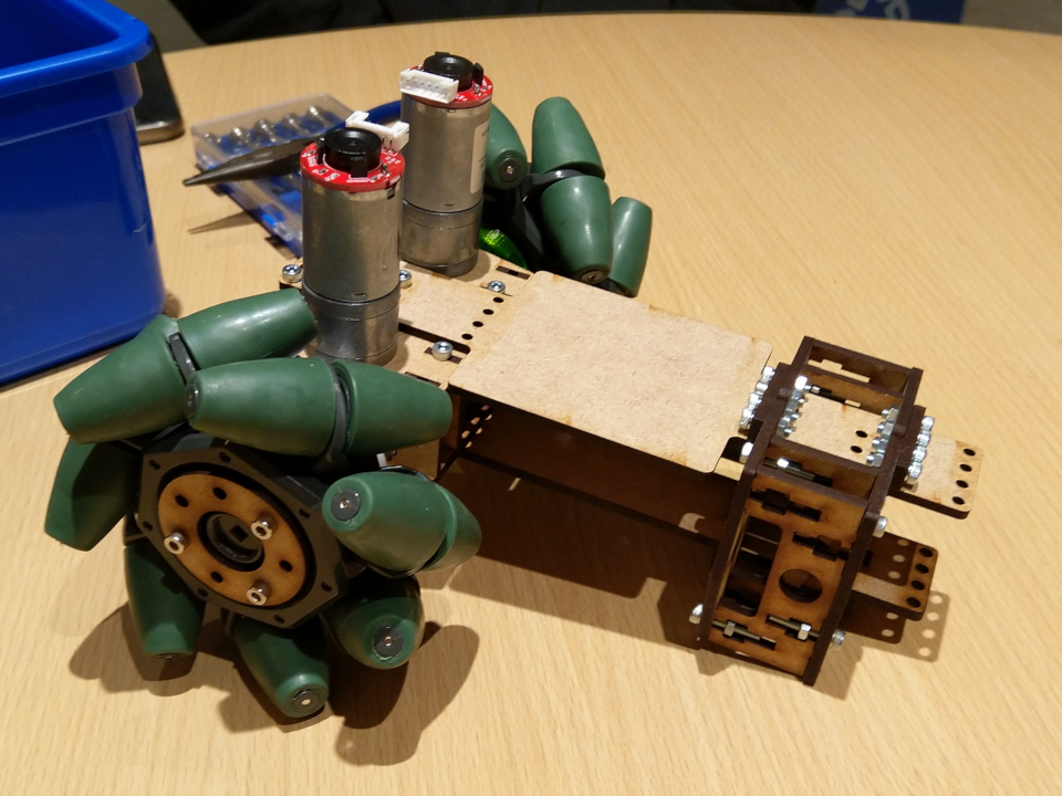
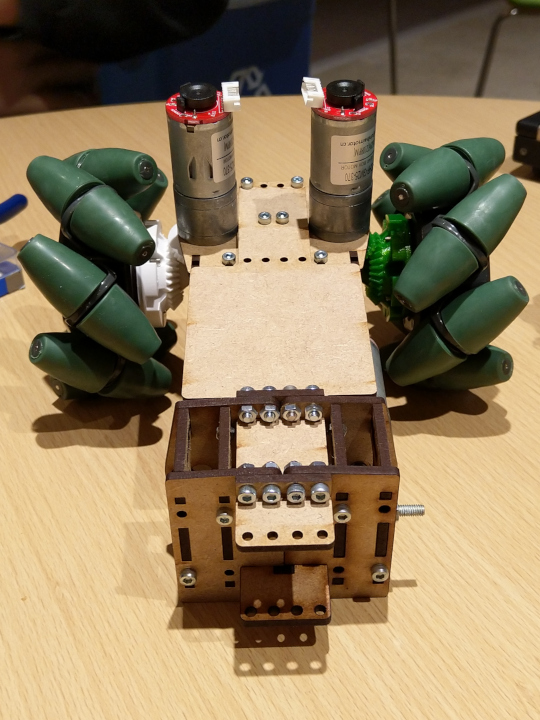
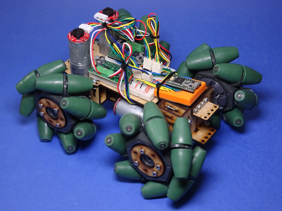
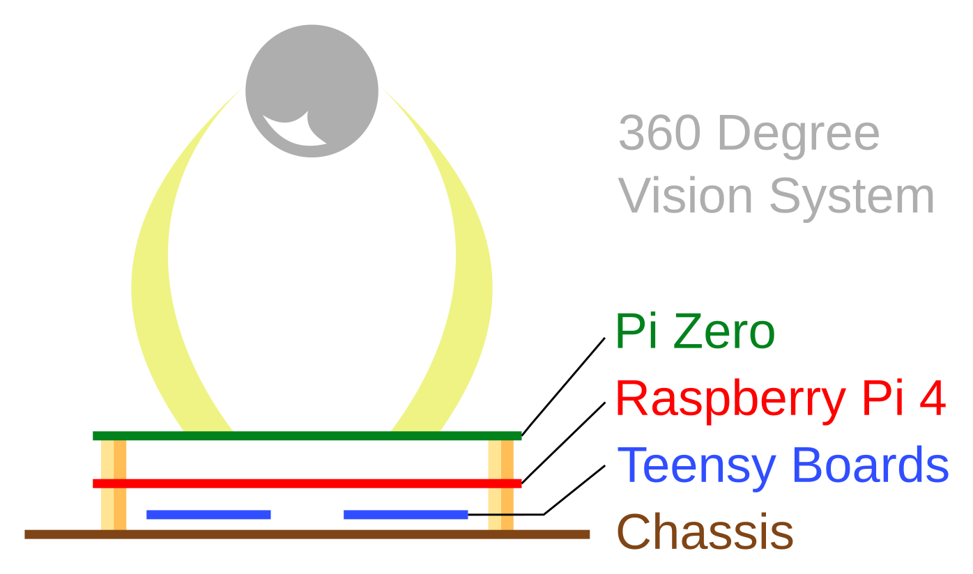
It’s a bit hard to see in the photos, but the chassis is made up of two layers of MDF for rigidity, with a space in between. The tentative plan is that middle layer will host the motor drivers and any other smaller electronics, likely an IMU. Batteries will go below the bottom layer. The Teensy boards we’re using for the motor encoders, motor PWM, remote control input decoding, some sensors, and as an I2C interface, would go on top. The main Raspberry Pi on top of them, then 360-degree camera on top of the Pi. Writing that out I realised it’s a bit hard to visualise, so I’ve included a diagram below. We’re trying to avoid the Pi’s native I2C due to the historical issues with it. For a reminder, the Teensy boards are needed for precise real-time timing and interrupts. We’ll have them communicate over USB to the Pi.
Continuing on the hardware side, I’m sad to report that Peter has retired from the team to focus on coursework and his other commitments as president of the Roboteers society. He was working on the gripper attachment. Robbie has volunteered to take that task over now that the chassis is finished. We were discussing at the last meeting how the gripper would be controlled, and we talked about the idea of having a 4-pin connector by the attachment mount on the front. This would expose the pins for I2C, SDA, SCL, plus GND, and +5V. Each attachment would then have something like an ATTiny85 (a simple microcontroller) or Arduino Nano (a bit more complex) to interface with any inputs/outputs the attachment needs. Then the gripper, launcher, and anything else, could be controlled via a relatively convenient interface and swapped out easily.
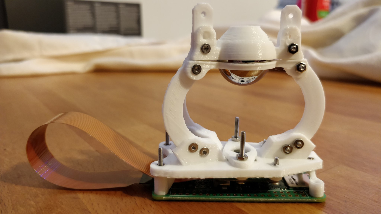
On the software side, work continues. Blayze has finished his 360-degree camera mount and is now set to work on the neural networks needed to interpret the image data.
Work on our control software, piwarsimulator also continues. We’re just about at the point where we can start planning moves in advance, which will let us be a bit smarter. This is implemented with a ‘movement_queue’ list that contains… a list of what we want the robot to do. Move, rotate, etc.. While the queue is running we’ll be processing sensor information to make sure we don’t get off track, i.e. collide with anything, and if we do, we’ll re-calculate. I sort of expect sensor information on things farther away to be less accurate, so I think we’ll set it to re-calculate ever few seconds as well, and update the movement_queue based on the newer sensor input. The ultimate goal is to be able to drift around a barrel.