Picking up speed
25 November 2019 - FredAfter a slow patch, we’re back in the game. Since my last post we’ve had some really encouraging progress. Unfortunately Harry had to send his apologies at our last in person meeting as he had other business to attend to. He also didn’t make much progress as the micro-controller he was testing interpreting radio controller signals with bricked itself. I hear it may be recoverable, and am looking forward to catching up on our electronics design at our next meeting.
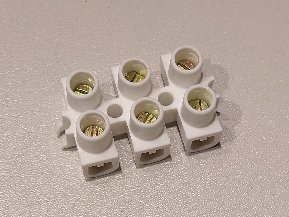
Moving along, we had some packages arrive! The most important one first, we now have our Pi Noon attachment block! I have to say, it’s been well worth the price of entry so far, and this is by far the nicest terminal block I’ve ever had my hands on.
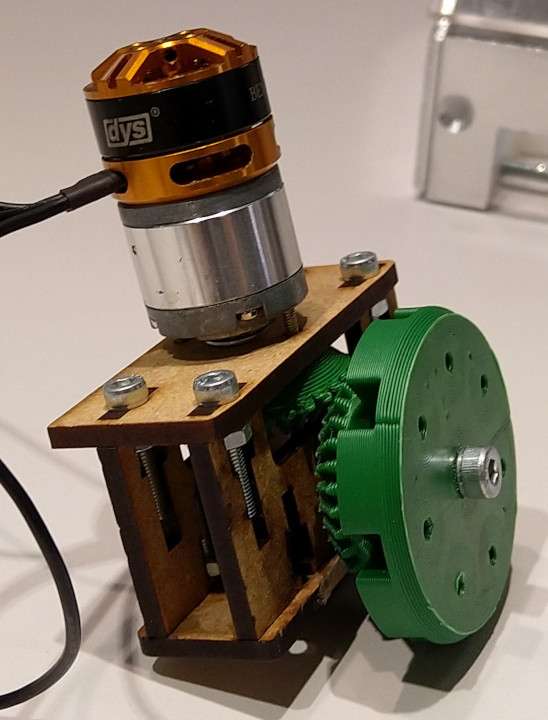
We’ve also had our motors arrive! This is just in time because Robbie has graced us with a working prototype of his bevel gear motor/mecanum wheel mount assembly. I got some footage of it spinning (apologies for the potato quality). The video shows the prototype with another motor installed for testing, but still! It spins! After seeing the assembly in action we had a few discussions about the vibrations the assembly produced and the strength of the gearing. This prototype was missing a bearing as it turns out M4 bearings are hard to source, but since the meeting Robbie has reported finding a lead on them. M5 also looks like an OK fall back. We’re now convinced the bevel drive system will work, and all we need then are the wheels to arrive and a chassis. Baby steps.

So chassis. Now that we have a mount assembly Robbie can work on getting the chassis together. I think I’ve mentioned this before, but there are two main design considerations for the chassis, a gripper and the camera mount. What about that attachment block? There are three main design considerations, a gripper, camera mount, attachment block, and launcher. There are four main design considerations… I’m sure you get the picture, there’s a fair bit to consider still, but we’re confident we can squeeze everything in. Peter is working on gripper development, and had a few thoughts on how tightly we might need to grip (loose) and if it needs two motors or one motor with some sort of linkages.
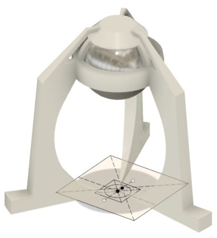
Continuing on design, Blayze now has a rough idea in CAD of what the camera mount could look like. As a reminder, the camera looks up and gets a 360-degree view. Based on this we’re currently thinking alien abduction for a disaster theme. Sadly three legs probably turn to four… Or is that a good thing?
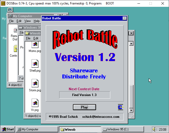
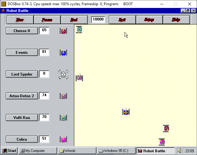
Myself, following up from investigating IMUs last week - those pesky inertial measurement units - I realised I was having a hard time working out how I would use an IMU when programming the robot. Which led me to thinking in more detail about how I would program the robot. I vaguely remembered playing around with a game when I was much younger (from computer camp?) that let you program virtual robots to fight with pseudo code. After much searching I found “Winrob.zip” on my hard drive, which contained a program called “Robot Battle” and was exactly what I remembered. It was a bit of a pain to get it working again (Windows 95 in DosBox!) but worth it to see (and hear!) it in action. It has very retro laser sound effects.
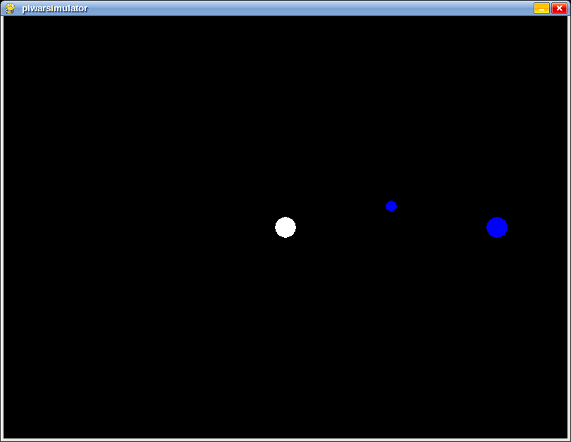
Based on how Robot Battle works, I’m writing on a simulator (in Python) to test out how our Pi Wars bot would move and solve the AI challenges. It’s called piwarsimulator and is available on GitHub as “piwarsimulator” - the mis-spelling is intention to make it easier to type. It doesn’t actually do any robot simulation yet, just renders the world. Currently the white dot is the robot, the small blue dot is a barrel, and the big blue dot is the zone to drop the barrel off at - a la Eco-Disaster. I hope something like this can encourage more teams to engage with the AI challenges, even if they don’t feel up to figuring out any complicated sensing via image processing or some such.
The last thing to talk about brings us full circle. If you recall that our motors arrived, they have encoders on them. The encoders are essential for accurate movement with mecanum wheels. Chris has been working on how to interpret encoder data and program mecanum wheel movement with that data using his mini-mecanum test platform, which we talked about a few weeks ago. He’s written something called a proportional integral derivate (PID) controller to use feedback from the encoder to precisely control the wheel angle. Look at it spin! (For background see Lance’s PiWarsMC talk.)
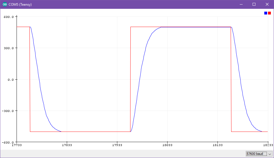
Diving into a little bit more detail, Chris sent me this graph that shows the requested wheel angle and the actual wheel angle moving towards it. This result after tuning the controller has the wheel moving with a slight delay, but without over-shooting, which is great for precise fine control. You can think of this type of PID position control a list of commands for the wheels. However, we’re more interested in moving the correct distance than having lots of specific orders carried out. So rather than control the angle of the wheel, we want to control the wheel’s velocity. This more gracefully handles things like wheel slip and as a bonus will let us more easily track position. Chris says he’ll be adapting his code to velocity control this week.
Moving forwards (at the correct velocity!) we should be at about the point where we have enough background work done (and materials) to really move forward on construction. I’m sure at our next meeting we’ll be ironing out those chassis details. In the meantime, general chassis work, gripper design, camera work, remote control, local logic, and precision movement work continue on.